SysML vs UML: Understanding the Differences
If you work in software, systems engineering, product development, aerospace, automotive, defense, medical devices, robotics, or any other complex engineering domain, you have probably heard of UML and SysML.
At first glance, thtey look similar. Both use diagrams. Both help teams visualize structure and behavior. Both are standardized modeling languages managed by the Object Management Group. And historically, SysML was built from UML.
But they are not the same.
The simplest way to think about it is this:
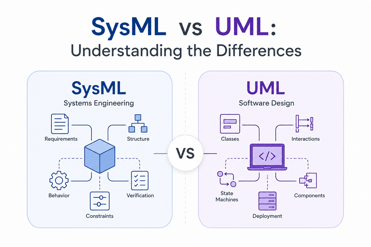
UML is mainly for software design. SysML is for systems engineering.
That difference matters because modern engineered products are rarely “just software.” A drone, satellite payload, medical device, radar system, autonomous vehicle, or industrial machine includes hardware, software, interfaces, operators, constraints, requirements, test cases, operating environments, and physical behavior. UML can describe some of this, but SysML was created to model the broader system.
To understand the difference properly, it helps to understand where both languages came from.
A Brief History of UML
UML stands for Unified Modeling Language.
Its story begins in the early 1990s, when object-oriented programming was becoming increasingly popular. At the time, many software engineers were using object-oriented languages such as C++ and Smalltalk, but there was no single standard way to visually model object-oriented software systems.
Different experts and companies had created their own modeling methods. This led to what is often called the “method wars,” where teams debated which notation and methodology should be used.
Three major methods became especially influential:
- The Booch Method, developed by Grady Booch at Rational Software
- Object Modeling Technique, or OMT, developed by James Rumbaugh and others at General Electric
- Object-Oriented Software Engineering, or OOSE, developed by Ivar Jacobson, known especially for use cases
These three people — Grady Booch, James Rumbaugh, and Ivar Jacobson — became known as the “Three Amigos.”
During the mid-1990s, they joined forces at Rational Software to create a unified modeling approach. The goal was not to create yet another competing method, but to consolidate the best ideas from existing object-oriented modeling methods into one common language.
This work eventually became UML.
In 1997, UML was submitted to and adopted by the Object Management Group, commonly known as OMG. OMG became the standards organization responsible for maintaining and evolving UML.
UML then became one of the most widely used visual modeling languages in software engineering. It gave software teams a shared notation for describing classes, objects, use cases, interactions, states, activities, components, and deployment structures.
In other words, UML emerged because software engineering needed a common visual language for object-oriented software design.
Key Players in the History of UML
Several individuals and organizations played important roles in the creation and standardization of UML.
Grady Booch
Grady Booch developed the Booch Method, one of the major object-oriented design methods that influenced UML. His work focused strongly on object-oriented analysis and design.
James Rumbaugh
James Rumbaugh was one of the creators of the Object Modeling Technique, or OMT. OMT contributed important structural modeling ideas to UML, especially around object and class modeling.
Ivar Jacobson
Ivar Jacobson created Object-Oriented Software Engineering, or OOSE. His work contributed the concept of use cases, which remain one of the most widely recognized parts of UML and SysML.
Rational Software
Rational Software brought Booch, Rumbaugh, and Jacobson together. It played a major role in developing and promoting UML during its early years.
Object Management Group
OMG adopted UML as a standard in 1997 and has maintained it since then. OMG’s role was important because it turned UML from a vendor-driven language into an industry standard.
A Brief History of SysML
SysML stands for Systems Modeling Language.
SysML came later than UML. Its origin is tied to the growth of model-based systems engineering, or MBSE.
By the late 1990s and early 2000s, many systems engineers saw the value of model-based approaches. UML had already become popular in software engineering, and some systems engineers began exploring whether UML could be adapted for broader systems engineering work.
However, UML was designed mainly for software. It did not naturally handle many systems engineering concerns, such as requirements traceability, physical components, engineering constraints, parametric relationships, hardware-software interfaces, and verification planning.
Systems engineers needed a modeling language that could represent the complete engineered system, not just software objects.
The need for SysML began to take shape through work by the International Council on Systems Engineering, or INCOSE, and the Object Management Group.
In the early 2000s, INCOSE and OMG collaborated to define what a systems engineering version of UML should support. This effort led to the OMG UML for Systems Engineering Request for Proposal, often called the UML for SE RFP.
A group called the SysML Partners formed in 2003 to respond to this need. The SysML Partners included systems engineering experts, software modeling experts, tool vendors, and industry participants. Their goal was to create a UML-based language suitable for systems engineering.
One of the central figures in this effort was Cris Kobryn, who had previously been involved in UML standardization work. Kobryn led the SysML Partners effort and is widely associated with the early organization and naming of SysML.
Other important contributors included Sanford Friedenthal, who was deeply involved in the SysML effort and later co-authored one of the most widely used SysML reference books, A Practical Guide to SysML, with Alan Moore and Rick Steiner.
OMG adopted SysML v1 in 2006, and the formal SysML 1.0 specification was released in 2007.
SysML was therefore born from a practical engineering need: systems engineers wanted the benefits of model-based design, but needed a language better suited to multidisciplinary systems.
Key Players in the History of SysML
INCOSE
The International Council on Systems Engineering played a major role in identifying the need for a systems engineering modeling language. INCOSE helped define the systems engineering requirements that SysML needed to satisfy.
Object Management Group
OMG provided the standardization process for SysML, just as it did for UML. OMG adopted SysML and continues to manage the SysML standard.
SysML Partners
The SysML Partners were an informal group of systems engineering experts, software modeling experts, vendors, and users who developed the original SysML specification proposal.
Cris Kobryn
Cris Kobryn led the SysML Partners effort and had prior leadership experience with UML standardization. He is a key figure in the early creation and organization of SysML.
Sanford Friedenthal
Sanford Friedenthal was one of the major contributors to SysML and helped organize the original SysML effort. He is also well known for his work in MBSE and for co-authoring A Practical Guide to SysML.
Alan Moore and Rick Steiner
Alan Moore and Rick Steiner, along with Sanford Friedenthal, helped explain and popularize SysML through A Practical Guide to SysML, which became a key reference for practitioners.
Tool Vendors and Industry Users
SysML was not developed only by academics or standards bodies. Tool vendors and industry users were important because SysML had to be practical enough to implement in modeling tools and useful enough for real engineering projects.
Why SysML Was Created from UML
SysML was not created completely from scratch.
Instead, it was built as a customization of UML for systems engineering. This was a practical choice because UML already had a mature modeling foundation, existing tool support, and a growing user base.
SysML reused some UML concepts, modified others, removed software-specific elements that were less useful for systems engineering, and added new concepts.
Some of the most important additions included:
- Requirements diagrams
- Block definition diagrams
- Internal block diagrams
- Parametric diagrams
- Stronger support for requirements traceability
- Better support for engineering constraints and system composition
This is why UML and SysML look related. They share historical roots, but their purposes are different.
What is UML?
UML is a general-purpose modeling language for software-intensive systems.
It is especially useful for describing:
- Software classes and objects
- Software components
- Interfaces between software modules
- Use cases and actors
- Sequence of software interactions
- State machines
- Deployment of software components
- Activity flows and logic
For example, a software team building an e-commerce application might use UML to model:
- User login behavior
- Order processing workflows
- Class relationships between
Customer,Order, andPayment - API interactions between the frontend, backend, and payment service
- State transitions for an order, such as “Created,” “Paid,” “Shipped,” and “Cancelled”
UML is therefore very strong when the main problem is software architecture and software behavior.
What is SysML?
SysML is a general-purpose modeling language for systems engineering.
It is used to model systems that may include:
- Hardware
- Software
- People
- Procedures
- Data
- Physical components
- Interfaces
- Requirements
- Constraints
- Verification activities
- System behavior
- System structure
- Engineering analyses
For example, a systems engineering team designing an EO/IR surveillance system might use SysML to model:
- The system context
- External actors and interfaces
- Requirements
- Hardware blocks such as camera, gimbal, processor, power supply, and operator interface
- Software functions
- Data flows
- State behavior
- Performance constraints
- Verification test cases
- Traceability from stakeholder needs to design and verification
SysML is therefore very strong when the main problem is engineering a complete system across disciplines.
The Key Difference: Software Model vs System Model
The biggest difference between UML and SysML is the scope of what they are intended to model.
UML is optimized for software-intensive design. It focuses heavily on object-oriented software concepts such as classes, objects, methods, software components, and software interactions.
SysML is optimized for systems engineering. It focuses on requirements, architecture, functions, interfaces, constraints, verification, and physical system composition.
A useful analogy is:
UML helps software teams design the application. SysML helps engineering teams design the product.
This does not mean UML is only useful for code or that SysML cannot model software. Instead, it means their center of gravity is different.
UML asks:
How should the software be structured, and how should software objects interact?
SysML asks:
What does the system need to do, what is it made of, how do the parts interact, what constraints apply, and how will we verify that it meets its requirements?
Diagram Types: What UML and SysML Have in Common
Because SysML was historically based on UML, there is overlap between the two languages. Both can represent structure and behavior.
Common modeling ideas include:
- Use cases
- Activities
- State machines
- Sequence interactions
- Packages
- Structural relationships
This overlap can make SysML feel familiar to people who already know UML. For example, both languages can describe how an operator interacts with a system, how a process flows from one step to another, or how a system changes state in response to events.
However, SysML modifies, removes, and adds concepts to make the language more appropriate for systems engineering.
What SysML Adds Beyond UML
SysML adds several important capabilities that UML does not emphasize in the same way.
1. Requirements Modeling
One of the most important additions in SysML is the ability to model requirements directly.
In SysML, requirements are not just text in a document. They can be part of the model and linked to design elements, test cases, functions, interfaces, and constraints.
This enables traceability such as:
- Stakeholder need → System requirement
- System requirement → Architecture element
- Requirement → Verification method
- Requirement → Test case
- Requirement → Risk or constraint
This is extremely valuable in regulated or safety-critical industries where teams must demonstrate that every requirement is implemented and verified.
UML can represent requirements using extensions or profiles, but requirements modeling is not one of its core strengths.
2. Blocks Instead of Classes
In UML, a core structural concept is the class. Classes are ideal for software because they describe objects, attributes, operations, and relationships.
In SysML, the equivalent core concept is the block.
A block is more general than a software class. It can represent almost anything in a system:
- A sensor
- A processor
- A battery
- A software function
- A mechanical assembly
- A vehicle
- A subsystem
- A human operator
- An external system
This makes SysML more natural for multidisciplinary engineering.
For example, in SysML, a block called UAV Surveillance System could contain blocks such as:
EO/IR PayloadGimbalMission ComputerPower SupplyOperator Control StationVideo ProcessorData Link
This is much closer to how systems engineers think about product architecture.
3. Internal Block Diagrams
SysML includes internal block diagrams to show how parts of a system are connected.
This is useful for modeling:
- Physical connections
- Data interfaces
- Power interfaces
- Mechanical interfaces
- Signal paths
- Item flows
- System composition
For example, an internal block diagram can show that a camera sends video to a processor, the processor sends metadata to a mission computer, and the power supply provides regulated power to multiple components.
UML component diagrams can show software component relationships, but SysML internal block diagrams are better suited for mixed hardware-software systems.
4. Parametric Diagrams
SysML includes parametric diagrams, which allow engineers to model equations, constraints, and engineering relationships.
This is especially useful for performance analysis and trade studies.
For example, a parametric model could represent:
- Power consumption
- Mass budget
- Thermal constraints
- Range equations
- Reliability equations
- Cost relationships
- Latency budgets
- Field-of-view calculations
This is a major difference from UML. UML is not designed to represent engineering equations and physical constraints in the same way.
Parametric modeling is one reason SysML is powerful for real engineering systems, not just software architecture.
5. Better Support for Verification and Validation
SysML supports relationships that help connect requirements to verification activities.
A model can show:
- What requirement is being verified
- What test case verifies it
- What design element satisfies it
- What analysis supports it
- What risk or constraint is related to it
This is important because systems engineering is not only about designing the system. It is also about proving that the system satisfies stakeholder needs.
For industries such as aerospace, defense, automotive, rail, medical devices, and nuclear systems, this traceability is often essential.
What UML Does Better
SysML is not automatically “better” than UML. It depends on the problem.
UML remains very useful when the main concern is software design.
UML is often better for:
- Object-oriented software architecture
- Class design
- Software component relationships
- API behavior
- Software sequence logic
- Software deployment views
- Code-oriented design discussions
A software team building a web application, mobile app, backend service, or microservice architecture may find UML more direct and familiar.
For example, if you are designing a payment processing service, UML class diagrams and sequence diagrams may be exactly what you need.
Using SysML for a purely software-focused problem may add unnecessary complexity.
What SysML Does Better
SysML is usually better when the problem crosses discipline boundaries.
SysML is often better for:
- Complex products
- Hardware-software systems
- Cyber-physical systems
- Safety-critical systems
- Requirements traceability
- Interface definition
- Verification planning
- System architecture
- Trade studies
- Performance constraints
- MBSE workflows
For example, if you are designing a drone detection system, SysML can model the radar, EO/IR camera, operator interface, software algorithms, power interfaces, external actors, requirements, and verification strategy in one connected model.
That is where SysML becomes valuable.
It gives teams a shared engineering model instead of separate disconnected documents, spreadsheets, drawings, and software diagrams.
SysML v1 vs SysML v2: Why This Matters
A modern discussion of SysML should also mention SysML v2.
SysML v1 was closely related to UML. In practical terms, many SysML v1 tools and methods inherited concepts from UML and adapted them for systems engineering.
SysML v2 is a major evolution. It is intended to improve precision, consistency, interoperability, and usability. One of the important changes is that SysML v2 is not simply “UML with systems engineering extensions.” It has a stronger semantic foundation and includes both graphical and textual ways to represent models.
This matters because SysML v2 is aimed at making system models more rigorous, machine-readable, and easier to integrate with engineering analysis, simulation, and automation.
For organizations adopting MBSE today, this raises an important strategic question:
Should we build only around SysML v1 practices, or should we prepare for SysML v2 and more model-driven engineering workflows?
The answer depends on tool maturity, project needs, customer expectations, and the organization’s current engineering process. But the direction is clear: systems engineering is becoming more digital, more connected, and more model-based.
Practical Example: Modeling a Drone Detection System
Imagine a team is developing a drone detection system.
A UML model might describe:
- Software classes for track management
- Sequence diagrams for radar track processing
- State machines for software modes
- Deployment diagrams showing software components on processors
This is useful, but it does not fully describe the system.
A SysML model could describe:
- Stakeholder needs
- System requirements
- Radar, EO/IR camera, operator station, network, and processor blocks
- Interfaces between sensors and processing units
- Power, data, and control flows
- Detection and tracking behavior
- Constraints such as range, latency, false alarm rate, and field of view
- Verification cases for detection range and classification performance
- Traceability from requirements to design and test
In this case, UML helps with the software design, while SysML helps with the full system architecture.
The best engineering teams may use both: SysML for system-level architecture and UML-like diagrams for software-level design.
Common Misconceptions
Misconception 1: SysML replaces UML
Not exactly.
SysML does not make UML obsolete. UML is still useful for software design. SysML is better suited for system-level engineering. They solve related but different problems.
Misconception 2: SysML is only for aerospace and defense
No.
SysML is common in aerospace and defense because those systems are complex and require traceability. But SysML is also useful in automotive, robotics, medical devices, industrial automation, energy systems, transportation, and consumer products.
Any product that combines hardware, software, people, constraints, and verification can benefit from SysML.
Misconception 3: Diagrams are the model
This is one of the biggest misunderstandings.
In MBSE, diagrams are views of the model. The model is the connected information underneath: requirements, elements, relationships, interfaces, constraints, behaviors, and verification links.
A diagram is useful because it helps humans understand part of the model. But the real value comes from the connected model data.
Misconception 4: SysML automatically creates good systems engineering
A modeling language is only a tool.
SysML can help, but it does not replace good requirements, architecture thinking, verification planning, interface control, trade studies, or stakeholder communication.
Poor engineering in SysML is still poor engineering.
When Should You Use UML?
Use UML when your main focus is software.
UML is a good fit when you need to model:
- Software architecture
- Class relationships
- Object interactions
- API behavior
- Software component deployment
- Application logic
- State behavior inside software
If your team is mostly software developers and your product is primarily software, UML may be sufficient.
When Should You Use SysML?
Use SysML when your main focus is the system.
SysML is a good fit when you need to model:
- Requirements
- System architecture
- Hardware-software interfaces
- Functional behavior
- Physical components
- Engineering constraints
- Verification and validation
- Traceability
- System-of-systems interactions
- Trade studies
If your team includes systems engineers, software engineers, hardware engineers, mechanical engineers, electrical engineers, test engineers, product managers, and customers, SysML is often the better fit.
Summary Table
| Topic | UML | SysML |
|---|---|---|
| Primary purpose | Software modeling | Systems engineering modeling |
| Main audience | Software engineers and architects | Systems engineers and multidisciplinary teams |
| Historical origin | Object-oriented software methods | MBSE and adaptation of UML for systems engineering |
| Key early figures | Grady Booch, James Rumbaugh, Ivar Jacobson | Cris Kobryn, Sanford Friedenthal, SysML Partners, INCOSE, OMG |
| Core structure element | Class | Block |
| Requirements modeling | Limited or extension-based | Built-in concept |
| Hardware modeling | Not the main focus | Strong fit |
| Software modeling | Strong fit | Supported, but not the only focus |
| Physical constraints | Limited | Supported through parametrics |
| Verification traceability | Limited | Stronger support |
| Best for | Software systems | Complex engineered systems |
| Common use cases | Applications, services, APIs, software design | Aerospace, defense, automotive, robotics, medical devices, industrial systems |
Final Thoughts
UML and SysML are related, but they serve different engineering needs.
UML came from the software world. It was created to unify competing object-oriented software modeling methods and give software engineers a common visual language.
SysML came from the systems engineering world. It was created because systems engineers needed a modeling language that could describe requirements, architecture, behavior, interfaces, constraints, and verification across hardware, software, people, and processes.
UML helps teams think about software structure and behavior. SysML helps teams think about the complete system.
For modern engineering organizations, the question should not always be “SysML or UML?”
A better question is:
What level of the problem are we modeling?
If the problem is software architecture, UML may be enough.
If the problem is a complex engineered product, SysML is likely the better choice.
If the product includes both system-level complexity and software complexity, both languages may have a role.
As engineering becomes more digital, model-based, and AI-assisted, understanding the difference between UML and SysML is becoming increasingly important. The future is not just about drawing diagrams. It is about creating connected engineering models that improve clarity, traceability, decision-making, and product quality.
At Ngenaire, this is exactly the kind of engineering transformation we care about: reducing busy work, improving engineering intelligence, and helping teams move from scattered documents to connected, model-based thinking.
Scholarly and Professional Sources
- Booch, G., Rumbaugh, J., & Jacobson, I. (1999). The Unified Modeling Language User Guide. Addison-Wesley.
- Rumbaugh, J., Jacobson, I., & Booch, G. (2004). The Unified Modeling Language Reference Manual.
- Kobryn, C. (1999). “UML 2001: A Standardization Odyssey.” Communications of the ACM, 42(10), 29–37.
- Object Management Group. OMG Unified Modeling Language Specification.
- Object Management Group. OMG Systems Modeling Language Specification.
- Friedenthal, S., Moore, A., & Steiner, R. (2014). A Practical Guide to SysML: The Systems Modeling Language. Morgan Kaufmann.
- Weilkiens, T. (2006). Systems Engineering with SysML/UML: Modeling, Analysis, Design. Morgan Kaufmann.
- Balmelli, L. (2007). “An Overview of the Systems Modeling Language for Products and Systems Development.” Journal of Object Technology, 6(6), 149–177.
- Hause, M. (2006). “The SysML Modelling Language Explained.” Artisan Software Tools / OMG SysML resources.
- INCOSE. Systems Engineering Vision 2035.
- Delligatti, L. (2014). SysML Distilled: A Brief Guide to the Systems Modeling Language. Addison-Wesley.
- Object Management Group. SysML v2 Specification and Overview Materials.